Ultraviolette (UV) Laser markieren Drahtkabel-Isolierungsmaterialien
Sep 16 , 2022According to IOP Handbook of Laser Technology, in 1999 approximately 22,000 laser marking machines were in use in various industries worldwide. Hexa Research expects overall laser market to reach $3bln USD in 2024. It seems quite possible that in a few years everything that needs to be marked will be marked with lasers including fruits and vegetables and most definitely wires and cables.
This article describes the basic principles of UV laser marking of wires and cables for aerospace industry and its applicability to other markets.
Direct printing on wires and cables with Ultra-violet (UV) lasers has been extensively tested and accepted within the aerospace industry both by OEMs and by the end users. It is covered by several documents and standards issued by SAE International and reflected in the production specification of large and small frame aircrafts for commercial, industrial, and military use. The OEM list includes Boeing, Airbus, Lockheed Martin, Sikorsky, Gulfstream, Bombardier, Pilatus, and many others. It is also used by governmental agencies such as DOD, NASA, FAA, etc. End users employ UV laser marking machines during scheduled maintenance and repair procedures.
UV lasers leave a permanent indelible high-resolution mark on the substrate surface. To understand the phenomenon, we must consider how a laser beam interacts with material. For example, the beam can be completely reflected from a surface, as a sun ray from a mirror, or propagate unaffected, as a sun ray through clear glass window. In these cases, no trace will be left on a surface. To mark a material, at least part of the laser radiation must be absorbed directly on or near the material’s surface.
Depending on laser and material properties there are a few possible scenarios (Fig.1):
The irradiated material evaporates, leaving relatively sharp border trenches on the surface.
The irradiated material melts and spills from the inside out, creating hills and valleys in the middle of a plain.
The irradiated material heats up and produces gaseous components that react with atmospheric oxygen, depositing a product of combustion (such as soot) on the surface.
Color change. The material changes color without any other visible surface modifications.
All of the above.

Fig.1. Laser-Surface Interactions.
Ablation is the cleanest way to alter the surface but provides low marking contrast because the affected area does not change color. Making deeper and wider marks improves legibility but reduces material integrity that is clearly unacceptable for aerospace applications. One possibility is applying additional layer of wire insolation and then selectively removing it exposing the undercoat of a different color, but this does not look very practical either.
Melting and burning marking processes are subject to long-term durability problems because the melted material and burned-out deposit may not stick well to the unaffected area. That resembles a 21st century hot stamping technique. Of course, this version is more advanced, flexible, and precise but it is still hot stamping with all its well-known deficiencies.
Color change can be an excellent solution under the conditions that it does not alter the material properties, provides sufficient contrast, good durability, and long-term stability. UV laser marking of aerospace wires and cables satisfies all these requirements.
Fig.2 shows ETFE, and PTFE insulated wires processed with Tri-Star Technologies M-100L-FG wire marking system. Well defined, legible prints stay intact even after extensive accelerated thermal aging.
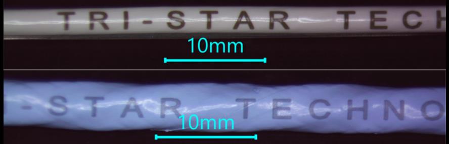
Fig.2. UV laser marking on ETFE (top) and PTFE (bottom) wires.
Marking cross sections (Fig.3) confirm that darkening zone extends 10-20um under the surface ensuring that marking cannot be altered or removed without physically destroying the top layer of the insulation.

Fig.3. Marked wire cross sections for BMS13-48T10C01G022 (left) and BMS13-60T44C01G022 (right).
The question is how a light-colored polymer surface turns dark under laser exposure without burning or melting. The answer is magic substance called Titanium Dioxide (TiO2). Luckily enough, this is a commonly used pigment that wire manufacturers use to make insulation look white or otherwise light-colored, such as gray, blue, green, yellow, pink, etc.
An optical band gap around 3.1 electron volts accounts for TiO2’s intense absorption of UV radiation with wavelengths shorter than 380 nanometers. Irradiation with a UV laser permanently turns TiO2 particles from white to blue/black. The same effect occurs when those particles are embedded into a substrate. Ideally, laser radiation does not react with the base material and passes freely through the substrate surface. In contrast, the pigment particles within the substrate interact with the laser beam that modifies the particles’ structure and appearance, including color. For example, thin PTFE films are practically transparent to the UV light while small (~0.3u) TiO2particles randomly distributed through the insulation layer strongly absorb the light and change color.
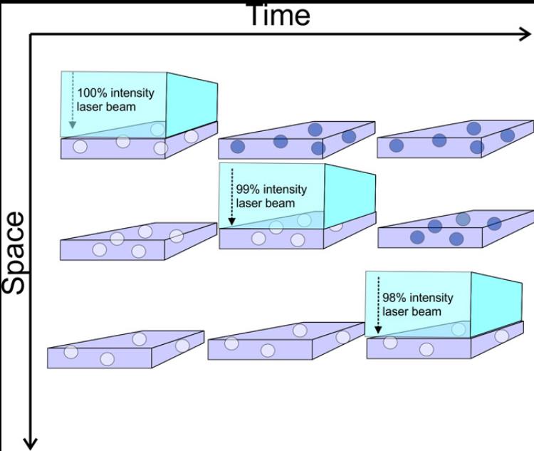
Abb.4 veranschaulicht den Prozess in Raum und Zeit. Ein einfallender Laserstrahl dringt ungehindert durch die erste Materialschicht ein und verliert einen kleinen Bruchteil (z. B. 1%) seiner Gesamtenergie bei der Wechselwirkung mit ursprünglich weißen TiO2-Partikeln, wodurch sie schwarz werden. Dasselbe geschieht auf der zweiten Schicht und so weiter, bis der größte Teil der Laserpulsenergie in den obersten 50-100 Schichten absorbiert wird. In Wirklichkeit ist der Prozess sowohl zeitlich als auch räumlich ziemlich begrenzt, da die Gesamtimpulsdauer normalerweise unter 30 ns liegt und die Markierungstiefe etwa 50 µm nicht überschreitet.
Abb.4. Schematische Darstellung des Strahlengangs eines UV-Lasers durch ein transparentes Medium, das mit TiO2-Partikeln dotiert ist.
Kurze Nanosekunden-Laserpulse verhindern einen regelmäßigen Wärmeaustausch zwischen den Additiven und dem umgebenden Material und begrenzen jegliche strukturelle und/oder chemische Modifikation der Pigmentpartikel selbst. Offensichtlich kann diese Markierung nicht leicht entfernt werden, da das meiste davon durch die obere Schicht verteilt ist, aber nicht auf der eigentlichen Oberfläche.
Die Frage, was genau mit TiO2-Partikeln unter intensiver UV-Lichteinwirkung passiert, würde den Rahmen dieses Artikels sprengen, aber die resultierende Farbänderung ist irreversibel. Beispielsweise wurde 1990 in den McDonnell Douglas Research Laboratories die Langzeitstabilität der UV-Lasermarkierung auf TiO2-dotierten ETFE-Filmen untersucht. Die Markierung zeigte wenig Veränderung während thermischer Alterung (770 Stunden bei 229 °C) oder simulierter Sonneneinstrahlung (entspricht 17 Jahren der UV-Exposition in der Wüste von Arizona).
Der Markierungskontrast ist proportional zur TiO2-Konzentration; Übermäßige Mengen können jedoch die Isolierung beschädigen. Normalerweise reichen 2–4 Gew.-% aus, um einen guten Kontrast zu erzielen. Tabelle 1 gibt typische Kontrastwerte an, die durch direktes UV-Laserdrucken auf Drahtkonstruktionen erreichbar sind, die üblicherweise in der Luft- und Raumfahrtindustrie verwendet werden.
Tabelle 1. Mit UV-Laser beschriftbare Drähte und Kabel
Aderspezifikation Farbe Isolierung Markierung Kontrast
BMS 13-48 Weißes extrudiertes XLETFE Ausgezeichnet
BMS 13-58 Graue PTFE-Bandumwicklung Gut
BMS 13-60 Weißes PTFE-Klebeband Gut
BMS 13-60 Grünes PTFE-Klebeband Marginal
M22759/05,06,08 Weißes extrudiertes PTFE Schlecht
M22759/07 Weißer Rand aus extrudiertem PTFE
M22759/09,10,11,12, 20,21,22,23,28,29,30,31 Weißer extrudierter TFE -Rand
M22759/16,17,18,19 Weißes extrudiertes ETFE Gut
M22759/32,33,35,41,42,44,45,46 Weißes extrudiertes XLETFE Sehr gut
M22759/34,43 Weißes extrudiertes XLETFE Ausgezeichnet
M22759/80,81,82,83,84,85,86,87,88,89,90,91,92 Weißes PTFE-Band Gut
M85485/5,6,9,10 Violettes extrudiertes XLETFE Sehr gut
M25038 Weißes PTFE-Klebeband Schlecht
M27500 SP2S23 Weißes extrudiertes XLETFE Sehr gut
M27500/20 L3T08 Weißes extrudiertes PVDF Ausgezeichnet
M27500/20 P2G23 Weißes PVC/ NYLON Sehr gut
M27500/22 C1G23 Weißes PVC/GLAS/NYLON Sehr gut
M27500/22 SP5S23 Weißes extrudiertes XLETFE Sehr gut
M27500/24 C3G23 Weißes PVC/GLAS/NYLON Sehr gut
M81044 Weißes extrudiertes PVDF Ausgezeichnet
Andere Drahttypen können ebenfalls markiert werden, solange sie das magische Pigment enthalten. Die Anforderung, TiO2 in der äußersten Schicht eines Mantels zu haben, ist die primäre Einschränkung für die oben beschriebene Markierungstechnologie. In den meisten Anwendungen wird TiO2 als weißes Pigmentierungsmittel verwendet und wird bei UV-Laserbestrahlung schwarz. Daher können nur helle Adern lesbar bedruckt werden.
Der Rest der Drähte kann auch mit einem Laser über die verschiedenen in Abb. 1 dargestellten Mechanismen markiert werden. Diese Markierungen werden jedoch höchstwahrscheinlich nicht den strengen Luft- und Raumfahrtstandards entsprechen, es sei denn, wir finden ein anderes magisches Pigment, das beispielsweise weiß wird von schwarz auf die grüne Laserbelichtung.